Energy monitor – 6 channels!
10th September 2025
If you dislike paying big bills for your electricity maybe a microcontroller project can help If you have a bit of interest in tinkering then you may be interested in this project where some of our club members have produced an energy monitoring system for the home.
This DIY project uses current sensors like this one
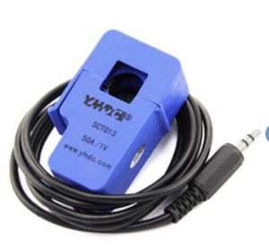
clipped over the wire inside your home switchboard. As such you will require a licenced electrician to finish this part of the install.
The project involved the design of a printed circuit board (PCB) which can handle 6 of these sensors enabling 6 separate power circuits of the home to be monitored. This could be for your main power circuits, your lights, air conditioner, hot water system or even your solar PV system.
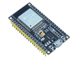
Chris H and a couple of other members put their heads together to re-design the board schematic which was originally inspired from this github project . It centres around a microcontroller board called an ESP32
and a very smart electronic chip
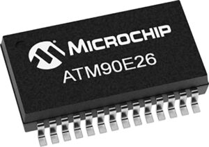
using two of these to provide for the six monitoring channels.
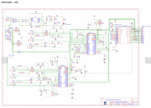
Chris tweaked the original design to his requirements and after many hours using the EasyEDA online design tool was able to produce a schematic diagram
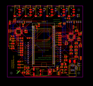 The tool helps with setting out the board layout but there is still a need to look closely at track layouts and try to minimise the track lengths and separations.
It has a Design Rule Check (DRC) that lets you know when there are incomplete connections, un-connected pins and pad-to-pad clearance concerns.
There are loads of other useful tips and things to check for as you work your way through the design.
Once the design process is completed and checked JLCPCB, the sister website of EasyEDA, (and other similar sites) makes component selection, procuring and subsequent board manufacturing easy. they can produce the bare PCB or you can order it “fully loaded” with all components professionally
The ESP32 one like this. with 38 pins. It gets it’s power from the PCB but could be separately powered from a 5V 2A supply. The actual power supply used is a 12VAC 2A transformer which serves 2 purposes. It’s AC waveform becomes one of the inputs to the ATM90E26 chips to provide the basis for calculating Power Factor. The other function is for rectifying to a5VDC supply on the board for the ESP32 and the other sections of the board.
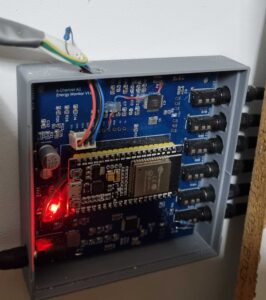 Last of all you can 3D print an enclosure for the assembled board that can be mounted somewhere close to your switchboard to keep things neat and tidy.
And here is the transformer in a nice box. 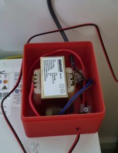
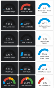
Since several of us use Home Assistant for automating things around the home we use a sub componentcalled ESPHome for the logic that configures the data available from the smart chip to display.
Send a note to microcontroller-workshopATmelbpcDOTorgDOTau if you are interested in taking part in this project..


