Building a CNC Router (Part 2)
19th June 2021
Dave Williams
This is the second part of a series of articles on Dave Williams’ experience of building a CNC (computerised numerical control) router, which is an automated cutting machine that can be used on materials such as wood, composites, aluminium etc.
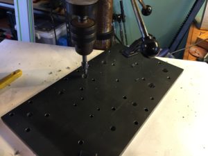
The laser cutting place was able to cut the steel and do the tapping for me, but they couldn’t do the counterbores, so I had to begin this relatively ‘boring’ process:
Here is the concept for how the base works; The two side plates are held parallel and straight by these aluminium profile pieces (which I will have to reinforce soon, but it should be rigid enough to get started). The two side plates are also bolted down to the base frame and can be adjusted and shimmed to make the two linear rails ‘planar’ if & when necessary:
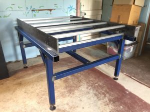
I’ve been using one of those laser levels to get it all level & planar to within a millimetre or two, I’ll see if I can come up with any other ways to get it even more accurate in future.
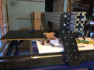
I’ve been doing a lot of ‘dry fit’ stuff with this build. It slows me down, but it’s nice to see it at least partially assembled as a kind of reward for all the mental (and physical) effort. I will need to dismantle it all again to get the various steel parts primed and painted, but I’m also becoming intimately familiar with how everything fits together, so that should be helpful with future maintenance and upgrades.
There are many things that I’ve glossed over here that did crop up throughout the process so far. For example, the linear rails were all too long, so I had to carefully cut them down with an angle grinder. The ball screws were machined to the exact right length, but the shoulder that fits in the fixed / driven bearing housing were too tight for me to get them on, so I had to set up a jig with a hand-drill and carefully lap them down with some wet and dry sandpaper. The steel plates are all a bit bowed, but luckily the way it’s constructed, that bow gets straightened when everything gets bolted together – for the gantry arms, I was able to place the inner and outer plates with an opposite bow and by bolting them together the bow was cancelled out. There is one plate ( The X-Axis Carriage) that doesn’t have anything to straighten it, so I will be attempting some ‘flame straightening’ methods with a boilermaker friend who has an oxyacetylene set. Look up flame straightening, it’s a fascinating technique, and able to correct (or create) some quite extreme bends in steel!
The gantry aluminium profile arrived the other day (finally), and so I’ve been able to get the whole gantry assembly put together as a dry fit:
It will all be driven by some closed-loop stepper motors with a decent amount of torque (9 & 12NM), because the gantry is rather heavy with all that steel. The spindle is a 2.2KW water cooled model and should be variable speed control via the software / g-code.
And that’s got us up to date with where I’m at!
I’ll be running everything with open-source firmware / software. I’ve sourced a control board / motion controller that is based on a more updated version of grbl called grblHAL (HAL stands for Hardware Abstraction Layer), so it can run on a whole variety of different microcontrollers. The Arduino nano version of grbl was maxed out in terms of capability (and memory!), and I wanted something that could be fourth-axis compatible in future.
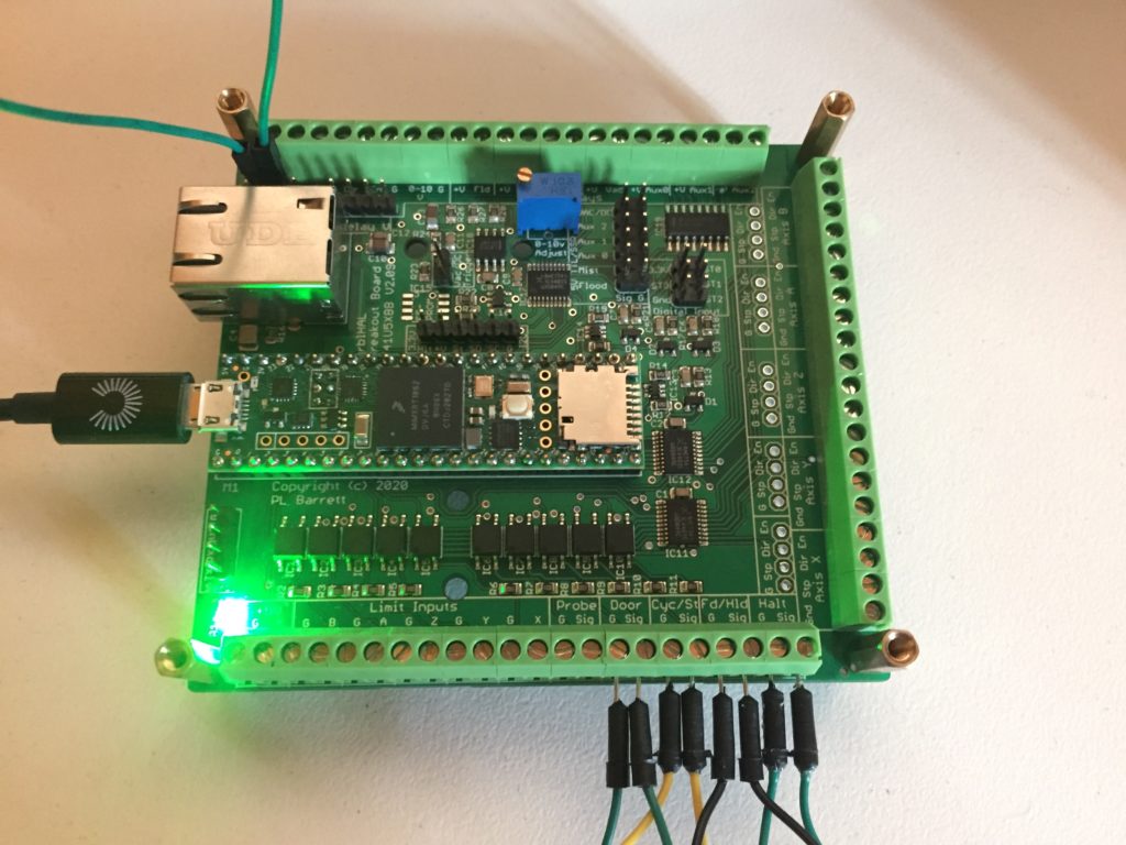
Based on a Teensy 4.1 MCU, and all manner of opto-isolated inputs and outputs included, also an ethernet interface, which I’ve yet to get working, but hopefully will allow a robust EMI resistant connection to the computer. It’s all open source and wasn’t expensive, considering how much CNC breakout boards can typically cost.
I have a couple of gcode senders to try out (like UGS), with varying levels of capability, and I did also manage to get a PC-only one sucessfully talking to the board from inside a windows VM set up via VirtualBox.
To be continued…