Dick Maybach, Brookdale Computer Users Group
Circuit simulation will interest only a few, but skimming through this article should impress you with the support a PC can provide for this specialized area. You likely have different interests, and it would probably be worth your while to search for equivalent tools appropriate for you.
When I began my electronics career many years ago, my design tools were pencil, paper, and a slide rule, and to check my circuits I used a soldering iron and a lab full of equipment, but now I can do all this on my PC using circuit simulation software. An easy introduction to circuit simulation is the free SimulIDE, https://www.simulide.com/p/home.html. Its main disadvantage is its documentation, which means you may have to approach it as though it were an adventure game. For instance, the examples weren’t available in my Linux version, and I had to extract them from a downloaded Windows version. Fortunately, SimulIDE is intuitive to use, making it a good starting point, and once you become acquainted with simulation, stepping up to more capable tools with their steeper learning curves, will be less daunting.
Figure 1 shows SimulIDE with a very simple circuit.
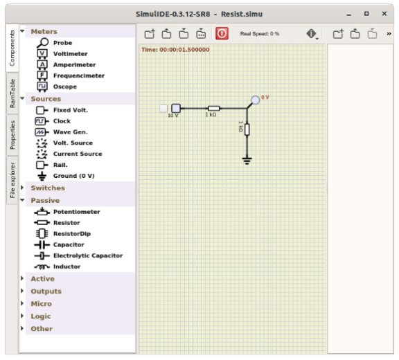
Figure 1. A Very Simple Circuit.
Create the circuit by dragging components from the left to the center panel. Right-click on a component and select Properties to change them from their defaults (5 Volts for the voltage source and 100 Ohms for the resistor). Left-click on a point to start a wire, move the cursor to where it should end, and left-click again to end it. You may notice that the circuit of Figure 1 doesn’t appear to be working. Ten volts is applied to the divider circuit, but the probe measures zero. This is because I haven’t turned on the fixed voltage source (by clicking on the small square to its left or started the simulation, by selecting the red power button at the top). I’ve corrected this in Figure 2, and the probe now reads five volts as it should. (The probe is not permanently connected, but can be moved as needed around the circuit.)
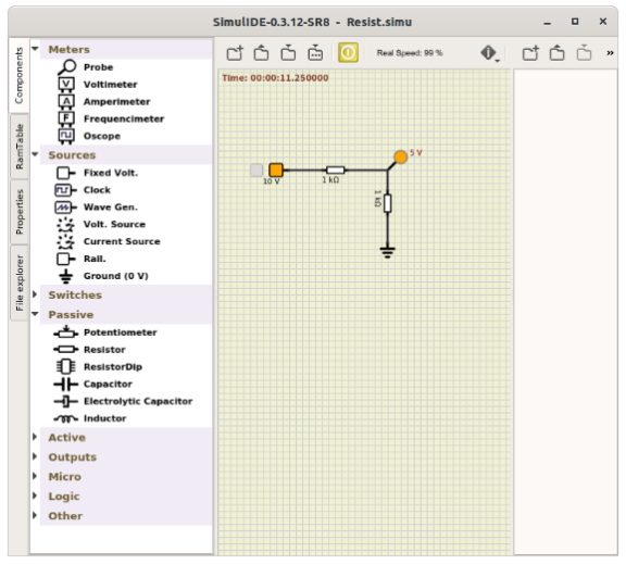
Figure 2. A Very Simple Circuit in Operation.
Turning on the source changed its color to orange, and starting the simulation did the same for the probe, which now displays the voltage at the point it touches. Figure 3 shows a slightly less trivial example.
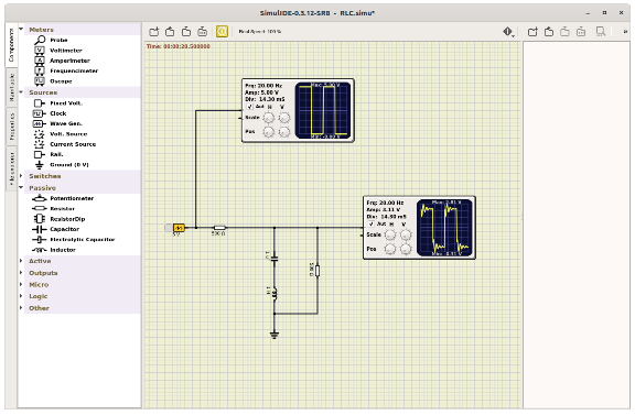
Figure 3. RLC Example.
Here the source is a wave generator set to produce a square wave, the detectors are oscilloscopes, and the circuit includes an inductor and a capacitor. I’ve found it necessary, after allowing the oscilloscopes to initialize, to turn off their auto feature. (Look carefully at the scope icons to see that Auto is not checked.) Then use the cursor to spin the horizontal and vertical scale controls (on the oscilloscope icons); you will probably have to make many revolutions of the knobs.
Of course, many circuits include active components, such as the one in Figure 4, which is an example included with the software.
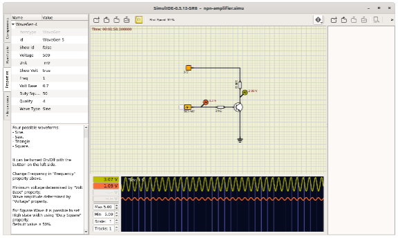
Figure 4. A Simple Active Circuit.
The wave generator is the same one used in Figure 3, but here, as shown by its properties in the left panel, it is set to produce a sine wave. There are also two probes shown, but their outputs are assigned to channel 1 and channel 2 of the plotter (by right-clicking on the icons to display their properties). This causes the waveforms they see to be displayed in the plotter windows, rather than the DC voltage they see being displayed next to their icon. We would obtain more accurate plots with the oscilloscope component used in Figure 3, but it’s often more convenient to use probes and their plotter function, as the latter can display up to four waveforms.
The program also simulates logic circuits, like the hexadecimal counter shown in Figure 5.
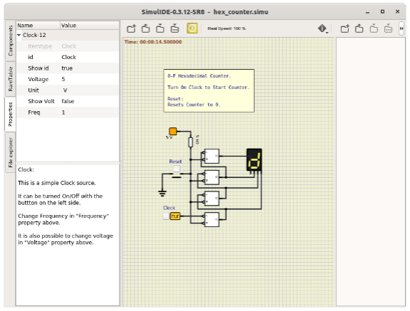
Figure 5. Hex Counter.
The clock is set to one Hertz, which causes the display to count continuously from 0 to F, changing once per second. Clicking on the Reset button forces the count to zero. More complex digital circuits are available, for example, five different Arduino models, one of which is shown in Figure 6.
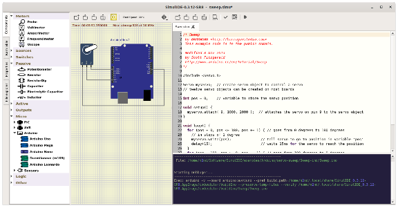
Figure 6. Arduino Simulation.
Here an Arduino Uno has been programmed to move a (white) servo arm back and forth over a 180-degree arc. The left panel shows the microprocessors available for use and, in particular the Arduino models. As usual, the center panel shows the circuit, while the program being run appears on the right, with a debug session below it. (You must have the Arduino IDE software installed to support it.) Unfortunately, the instructions I’ve found on simulating Arduino processors are specific to the Windows version of SimulIDE, and so far I haven’t found how to program the processor simulation in Linux.
SimulIDE is a good tool for the home experimenter, but it does have limitations. For example, there are only a few transistor models, and these aren’t adequate for radio-frequency design. However, it is a good starting point, as it’s easy to learn. I’ve begun experimenting with KiCad, https://kicad-pcb.org/, which is much more competent. As a result, it’s also more difficult to learn, but extensive tutorials are available on their website. Many professional circuit designers use Orcad’s PSpice, but its price puts it far out of the reach of home users. A free version is available to students, which is a good choice if you qualify. (Non-students can find a pirate version, but putting one of these on your PC is never a good idea.)